Project Goal and Purpose
Introduce myself to basic radio frequency (RF) design with a simple amplitude modulator and radio transmitter, based on a 555 timer generating a square carrier wave.
AM Theory
The basis of the transmitter is creating a predictable carrier wave which is higher in amplitude than the signal, and using the signal to modulate (to impose original audio signal on) the carrier wave.
A benefit of using a carrier wave is we can send lower frequency audio signals (i.e human speaking in the hundreds of Hz) on higher frequencies (even VLF is from 3 kHz - 30 kHz), which allows radio travel of longer travel distances.
Circuit Design
My design was based on designs and calculations from electronicsforu, which used the control voltage pin of the 555 IC to receive audio signal, and a 9V battery connected to some resistors to tune the frequency of the generated carrier wave
I made a few changes to the design. First, I replaced the condenser mic with an audio signal from my laptop, with the circuit connected to only the ring and sleeve (right channel and ground) of the 3.5mm port, to get mono audio.
I also added a 100u ceramic cap to the "antenna" to act as a high pass filter for interference coming from the 60V DC. As I did not have the equipment to listen (AM receiver capable of 130 kHz), I left off the 2-3m copper wire antenna and just measured signal off the end of a jumper wire.
The projected frequency of this circuit, using the same resistor values, should have been around 500-600 kHz. Unfortunately, potentially due to resistance in the breadboard I used, old capacitors, or DC coupling, I only received 131 kHz from the transmitter.
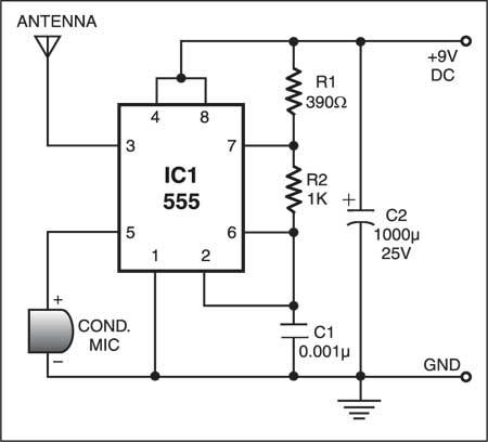
Photo and initial schematic credit: ElectornicsForU.com